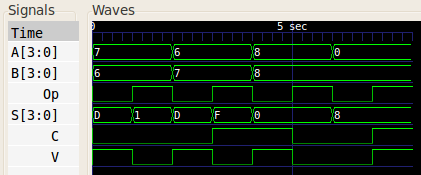
Pick the one that seem most interesting to you. Next is a logical description, where we express the outputs in terms of their logical equation. One is functionalas illustrated in the next subsection. We now have several options to define this adder.
VERILOG CODE FOR ADDER SUBTRACTOR HOW TO
It shows how to use two modules, one for the basic 3-bit full-adder adding a to b with carry-inand one that uses 4 of them to create a 4-bit adder with an output carry.Ī full adder is a combinational logic that takes 3 bits, aband carry-inand outputs their sum, in the form of two bits, carry-outand sum. This lab should be done after the introduction lab on Verilog. Podcast Programming tutorials can be a real drag. Intermatic px100 pool light 100 watt safety transformerĪmritanjan Kumar Amritanjan Kumar 1. Prashant Pimpale 7, 5 5 gold badges 18 18 silver badges 53 53 bronze badges. But it is not working for another test case.
VERILOG CODE FOR ADDER SUBTRACTOR CODE
I have edited the code and it works for 1 test case. Subhadip Subhadip 1 1 1 gold badge 1 1 silver badge 6 6 bronze badges. However, your second statement contains most of the solution to the problem. It also doesn't make sense to put it in an always block, since the rtl is defined in the modules already. So your first statement in the case of the subtraction bit being low doesn't really make sense. You can't instantiate modules conditionally because at compile time we don't know if that condition will be met or not. What you seem to not understand is that in Verilog your design is synthesized at compile time, not at run time.

Then I am using that to write code for 4 bit adder subtractor. I am using structural design.Īt first I have written verilog code for 1 bit full adder. I am writing verilog code for 4 bit adder subtractor. Stack Overflow for Teams is a private, secure spot for you and your coworkers to find and share information.

Design of 8 : 3 Parity Encoder using conditional o Design of 8 nibble queue using Behavior Modeling S Design of 8 nibble Stack using Behavior Modeling S Design of 4 Bit Adder cum Subtractor using Loops Design of Integer Counter using Behavior Modeling Design of Frequency Divider Divide by 10 using B Design of Frequency Divider Divide by 8 using Be Design of Frequency Divider Divide by 4 using Be Design of Frequency Divider Divide by 2 using Be Design of 4 Bit Comparator using Behavior Modeling Small Description about Behavior Modeling Style in Design of 4 to 1 Multiplexer using case statements Design of 2 to 4 Decoder using if-else statements Design of 4 to 2 Encoder using if -else statements Design of 4 to 1 Multiplexer using if -else statem Design of 4 Bit Adder cum Subtractor using xor Gat Design of 4 Bit Adder cum Subtractor using Structu Design of 4 Bit Subtractor using Structural Modeli Design of 2 to 1 Multiplexer using Gate Level Mode Design of 2 Bit Comparator using Conditional OperaBy using our site, you acknowledge that you have read and understand our Cookie PolicyPrivacy Policyand our Terms of Service. About Me Unknown View my complete profile. Load Comments.There is a mistake in subtractor code wire l is not defined. Check out this Author's contributed articles. Please Improve this article if you find anything incorrect by clicking on the "Improve Article" button below. See your article appearing on the GeeksforGeeks main page and help other Geeks. If you like GeeksforGeeks and would like to contribute, you can also write an article using contribute. S1, S2, S3 are recorded to form the result with S0. The carry C1, C2 are serially passed to the successive full adder as one of the inputs. A1, A2, A3 are direct inputs to the second, third and fourth full adders. 4-bit binary Adder-SubtractorĪs shown in the figure, the first full adder has control line directly as its input input carry C0The input A0 The least significant bit of A is directly input in the full adder. There is a control line K that holds a binary value of either 0 or 1 which determines that the operation being carried out is addition or subtraction. The circuit consists of 4 full adders since we are performing operation on 4-bit numbers.
+module+fa(sum%2C+co%2C+a%2C+b%2C+ci)+%3B+input+[3%3A0]+a%2C+b+%3B.jpg)
Lets consider two 4-bit binary numbers A and B as inputs to the Digital Circuit for the operation with digits. The operation being performed depends upon the binary value the control signal holds. In Digital Circuits, A Binary Adder-Subtractor is one which is capable of both addition and subtraction of binary numbers in one circuit itself.


 0 kommentar(er)
